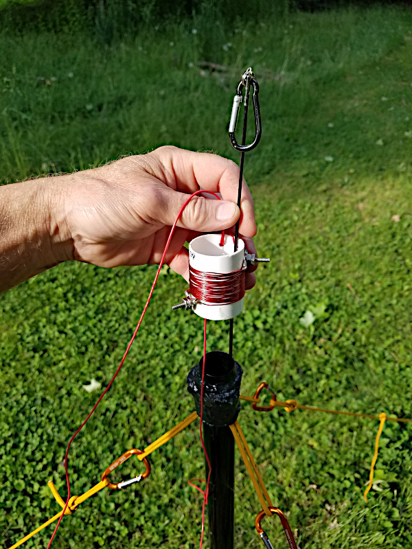
When setting up the shortened vertical, I have found that its best to run the fishing pole through the center of the coil. This reduces bending and stress on the fishing pole. Something else I have done is I labeled the one end of the loading coil as “top”. This is a result of my putting the loading coil upside down a couple of times when setting it up..

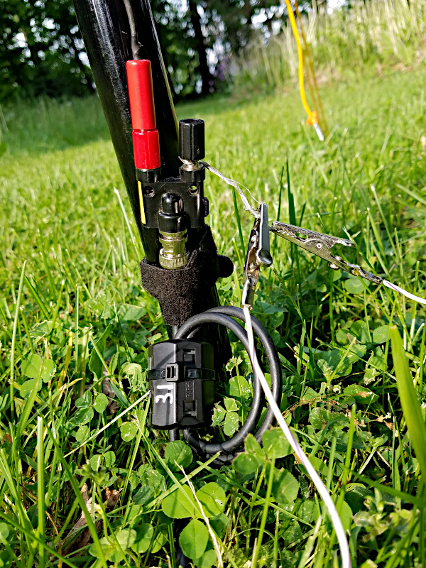
At the bottom of the fishing pole I use a BNC to dual Banana plug adapter as shown in the photo below. I also like to wrap the coax with a Type 31 Ferrite. I also like to label my ferrites with the mix that it is made of with a silver sharpie. I can’t tell you how many times I re-use a ferrite and forget what mix it is. You can also see that coming off the black binding post is some braided shield that is from a left over piece of RG-58 coax. The alligator clips go to my radials. This setup makes it quick and easy to deploy the radials. Of which I only use 2 radials with each one being 33 feet long. Yes 4 or more would be better, but I have had good success with just two radials running just 3 watts of power. The end of the RG-58 coax used for the feedline has a velcro strap on it which goes around the bottom of the fishing pole.

May i know if the radials requires elevation above the ground or just leave it laying on the ground?
Hello,
I always lay them on the ground simply because it is easier. If the radials are elevated, it will perform better. Even though elevating the radials gives better performance, I have not been disappointed with this antenna’s performance with the radials on the ground.
Hope this helps.
— Mike WB8ERJ
Mike
Thanks for the inspiration – I have parts on the way to build one – I’m an antenna neophyte – I noticed you don’t have any kind of transformer or inductor on the antenna input – is this simply a function of the loaded vertical design? (Whereas with an EFHW one is needed)
Thanks!
Michael
KD7PTZ
Hello Michael,
Thanks for checking out my blog. You are correct. There is no need for a transformer on a vertical since its impedance at resonance is close to 50 ohms. Actually between 35 and 70 ohms depending on the radial orientation, but not to worry about that. There are too many other uncontrollable factors in the real world of antennas to be concerned with that.
With an EFHW antenna since it is fed at the end of the antenna, the impedance there is 2000 – 3000 ohms. So in order to match the antenna to the coax / rig, you need a transformer on an EFHW antenna to get it down to 50 ohms. Hope that helps.
Good luck with your build – hope to work you someday.
— Mike WB8ERJ
Thanks Mike – I shot you a follow up email to your address on QRZ
Michael
KD7PTZ
Nice article, clear explanations. Looking further on your blog site, lots of nice articles!!!
For the past 2 years I have been loving random length and half wave end fed antennas on 9:1 / 49:1 Ununs. Really supriised what 34′ of wire can do add a counterpoise and/or a 1:1 to get rid of the feedline current
Now after reading this my next antenna is going to be a vertical!!!
Hope to work you
73 Ben – ne5B
Thanks Ben for the kind words. Yes I too have used an end fed wire. They work great! Probably better than a vertical. However I find setup and tear down of vertical antenna to be faster and easier with only a slight sacrifice in performance to an end fed wire.
Hope to work you on a POTA activation!
73’s — Mike WB8ERJ
Hello,
Im sorry for stupit question but:
“Diameter of the CONDUCTOR in inches”, from “Coil-Shortened Vertical Antenna Calculator”
Diameter of conductor – means the diameter of the lower and upper wire connected to loading coil, or diameter of the cooper wire used from loading coil ?
Many Thanks .
Martin
Hello,
I can see your point of confusion. “Diameter of conductor” means diameter of the coil.
Good luck!
— Mike
Many thanks for the clarification Mike.
Martin, OK5MCA
You are welcome!