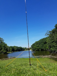
 Recently I went on vacation to Virginia and wanted to do some POTA activations using my new QCX-mini transceiver. On this trip I wanted to hike up to the summits of various mountains that are in various national parks. Since my QCX-mini is the 40 meter version, I obviously needed an antenna for it. My personal preference for portable antennas is to use vertical antennas as opposed to a dipole or other horizontally based antenna. Since my QCX-mini is 40 meters, a full sized vertical, being approximately 33 feet high, is a bit impractical.
UPDATE: I have built a new version of this antenna that covers 40 through 20 meters. If you are interested in building a 3 band version of this shortened vertical, click here.
I have seen others using collapsible fishing poles for antenna masts, so I figured I would give it a try. I found on Amazon.com a 20 ft. Crappie Fishing pole that collapses down to just 4 feet. I also found a web site that calculates what is needed for a coil shortened vertical antenna – perfect!
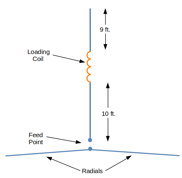
From what I have read, a base loaded vertical is less efficient than one that has the loading coil that is more near the top. The downside of placing the loading coil higher is that it needs to be larger, which will add to the weight, as well as additional stress on the pole in windy conditions. What I decided on was placing the loading coil slightly higher than the center of the vertical antenna.
Given my design constraints and using the coil shortened vertical antenna calculator, I settled on my shortened vertical antenna design. The diagram below is what I came up with:

For the loading coil form I decided to use an In Sink Tailpiece. My reasoning is this, typically people use standard PVC pipe for the coil form, which is fine, but the wall thickness of the pipe seems unnecessarily thick for my application. My main concern here was to put less stress on the wire that is the vertical part of the antenna. A toilet overflow tube is much thinner and lighter and works just fine. The outside diameter of my overflow tube is 1.5 inches. I am assuming that is a typical outside diameter.
I used the coil shortened vertical antenna calculator based on where the coil is to be located in the above diagram and came up with 23 1/2 turns of # 24 enamel wire. I used 24 gage wire because I had it on hand. If you have a different gage wire, put that in the coil shortened vertical antenna calculator instead.
May i know if the radials requires elevation above the ground or just leave it laying on the ground?
Hello,
I always lay them on the ground simply because it is easier. If the radials are elevated, it will perform better. Even though elevating the radials gives better performance, I have not been disappointed with this antenna’s performance with the radials on the ground.
Hope this helps.
— Mike WB8ERJ
Mike
Thanks for the inspiration – I have parts on the way to build one – I’m an antenna neophyte – I noticed you don’t have any kind of transformer or inductor on the antenna input – is this simply a function of the loaded vertical design? (Whereas with an EFHW one is needed)
Thanks!
Michael
KD7PTZ
Hello Michael,
Thanks for checking out my blog. You are correct. There is no need for a transformer on a vertical since its impedance at resonance is close to 50 ohms. Actually between 35 and 70 ohms depending on the radial orientation, but not to worry about that. There are too many other uncontrollable factors in the real world of antennas to be concerned with that.
With an EFHW antenna since it is fed at the end of the antenna, the impedance there is 2000 – 3000 ohms. So in order to match the antenna to the coax / rig, you need a transformer on an EFHW antenna to get it down to 50 ohms. Hope that helps.
Good luck with your build – hope to work you someday.
— Mike WB8ERJ
Thanks Mike – I shot you a follow up email to your address on QRZ
Michael
KD7PTZ
Nice article, clear explanations. Looking further on your blog site, lots of nice articles!!!
For the past 2 years I have been loving random length and half wave end fed antennas on 9:1 / 49:1 Ununs. Really supriised what 34′ of wire can do add a counterpoise and/or a 1:1 to get rid of the feedline current
Now after reading this my next antenna is going to be a vertical!!!
Hope to work you
73 Ben – ne5B
Thanks Ben for the kind words. Yes I too have used an end fed wire. They work great! Probably better than a vertical. However I find setup and tear down of vertical antenna to be faster and easier with only a slight sacrifice in performance to an end fed wire.
Hope to work you on a POTA activation!
73’s — Mike WB8ERJ
Hello,
Im sorry for stupit question but:
“Diameter of the CONDUCTOR in inches”, from “Coil-Shortened Vertical Antenna Calculator”
Diameter of conductor – means the diameter of the lower and upper wire connected to loading coil, or diameter of the cooper wire used from loading coil ?
Many Thanks .
Martin
Hello,
I can see your point of confusion. “Diameter of conductor” means diameter of the coil.
Good luck!
— Mike
Many thanks for the clarification Mike.
Martin, OK5MCA
You are welcome!