 Recently at work, I had the opportunity (or need) to make a phasing harness for a two bay antenna. But I had a problem. I found on the web a few years back how to do this for my particular antenna situation, but now the web page was gone! So I had to figure it out on my own. After many hours of looking through my (very poor) notes, I figured it out.
What I had was a pair of circular polarized antennas that were to be set up as a two bay antenna system. Each antenna had an impedance of 100 ohms. Here is what I came up with, and it seems to work.
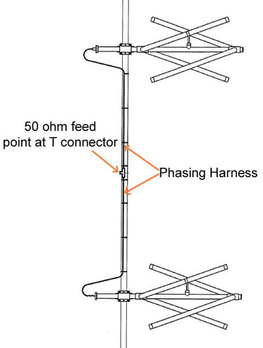
In a transmission line, such as coax, the impedance of the load repeats itself every half wavelength. Since each antenna is tuned to 100 ohms at resonance, all I have to do is cut two lengths of coax exactly to a multiple of a half wavelength, and connect them to a Tee connector. What this does is takes the two 100 ohm impedances of each antenna and put them in parallel with each other. The end result is a 50 ohm feed point, which allows me to connect my 50 ohm coax for proper match.
However there is one problem. When coax is manufactured, there is a 10% tolerance in the velocity factor of the coax. So as far as I am concerned, just taking the published velocity factor of the coax could be problematic. So I needed a way to measure or tune the individual lengths of coax to some multiple of a half wavelength.
By way of background, here is a diagram that is similar to the antenna system I was setting up. The two pieces of coax I had to precisely cut are labeled “Phasing Harness“:

So what I had on hand was Belden 8237 RG-8-U Type coax. This has a velocity factor of 0.66 and a characteristic impedance of 52 ohms. So based on these numbers, and the spacing between the two antenna bays, I chose to use a length of coax that is 7 half wavelengths long. Actually this is way too long for my needs, but that’s ok.
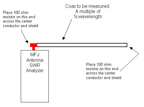
Here is what I came up with, I will simulate both antennas at resonance with a non-reactive 100 ohm resistor. So I built my own dummy load inside of a male type-N connector, as well as on the back of a female type-N connector. Next, I calculated the electrical half wavelength of a piece coax using the following formula:
L (inches) = (5904 * VelFactor) / Freq. (mHz)
This will give you the length for one half wavelength. In my case, I chose 7 half wavelengths, so I multiplied the result by 7, then added about 15%. This length is deliberately too long so I can tune it in to the desired frequency. On one end of the coax, I put a connector on it. The other end is the end that I will be trimming to length. So on this end, I put a connector on it, but I don’t solder it, which is ok for temporarily measuring its length.
Here is a diagram of my test setup using a MFJ-209 antenna analyzer:

Start your frequency sweep slightly above your desired frequency, then start sweeping down. As you tune through the frequency range, you will find a point where the SWR goes to almost 1 to 1. Typically I sweep the frequency several times to the low point of the SWR in both directions. This insures an accurate frequency reading for the coax. Make a note of the frequency.
Next, trim the coax by an inch, and repeat the steps above until the SWR dips at the same frequency as your antennas are resonant for. Do this for both pieces of coax, which comprises the phasing harness.
When you are through with both pieces of coax, you now have a completed phasing harness tuned to the same frequency of your antennas.
This article was originally posted on www.mikestechblog.com Any reproduction on any other site is prohibited and a violation of copyright laws