Like I said earlier, I chose to use the diamond configuration because you only need one support at the apex. To keep the loop in a diamond shape, I used two orange fiberglass driveway markers that you can pick up at the hardware store. I cut them each down to a length of 39 1/2 inches. By the way, use a hacksaw to cut them. Cutting fiberglass with any kind of wood saw will dull it before you finish cutting the fiberglass.
After you have cut the fiberglass poles I highly recommend taking some super glue and generously coating the cut end with it. Its real easy for the loose fibers at the end to get lodged in your hand – which is very painful!
Next I took a piece of scrap 3/4 inch thick wood and cut it 5″ long and 1″ wide and then drilled a 5/16″ hole 1 inch deep on each end of the wood. The holes are for sliding the rods into and the wood will be in the center of the loop.
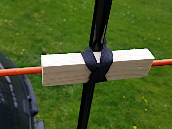
Here is a photo of the piece of wood with the fiberglass poles inserted in each end.

You can also see that I have attached two velcro strips to the center of the wood block. this way I can strap it to the pole which helps keep this block from sliding down the pole and causing the loop to sag.
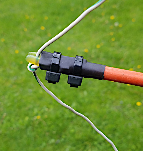
To attach the ends of the spreaders to the sides of the loop, I took the nock off the rear end of an arrow and attached it to the end of the rod that will support the wire. I happened to have a couple of arrows that were given to me so I already had some. You can probably get them at a sports store or if you know someone with some old arrows they don’t want anymore. To remove the nock, just grab it with a pair of pliers and twist & pull. They can be a bit tight, but they will come off.
Here is a photo of the end of the fiberglass spreader that shows the nock. To attach it to the rod, I just used heat shrink and then slid the cut ends of zip ties parallel with the rod inside the heat shrink. Then apply heat to shrink. Finally I added two zip ties around the outside. one to the nock, and the other to the rod.

In order to hold the nock at the right spot on the wire, I tied a knot for it to sit on. This point isn’t critical, so just measure down 1/4 the distance of the total wire length from the top and tie the knot. Do this before you proceed to the next step.
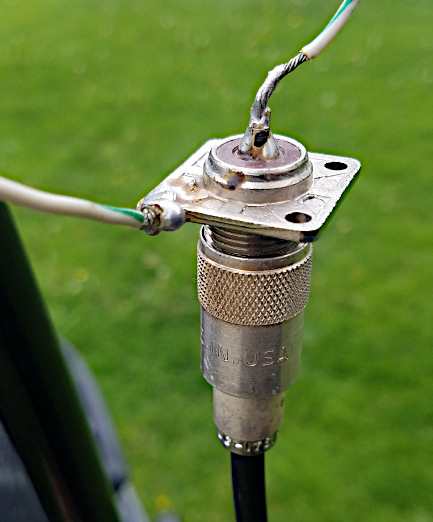
At the bottom, I took an SO-239 connector and soldered one end of the wire to the center, and the other end of the wire to one of its mounting holes as shown below:

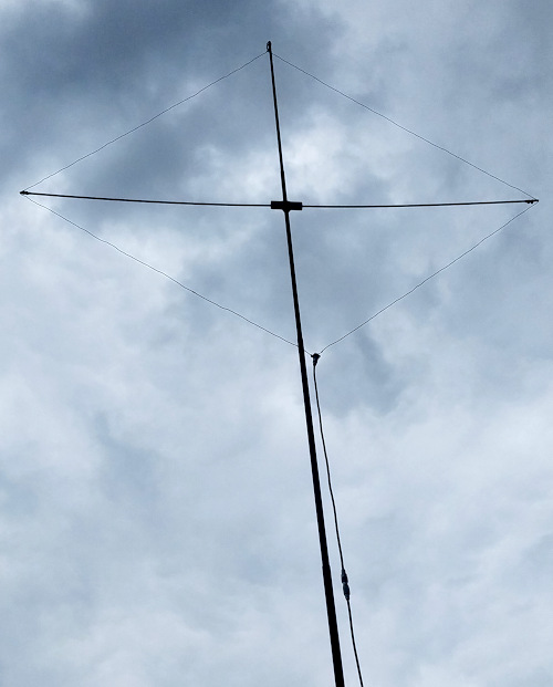
Here is a photo of the loop fully assembled and about 20 feet above the ground. If you are planning on using a spiderbeam like I do I wouldn’t go much higher. If its even slightly windy, I would go lower. Its not easy to see the wires, but if you look closely, they are there.

The SWR is 1.2 to 1 at resonance. The maximum radiation is bi-directional perpendicular to the plane of the loop. For a quick and easy POTA activation on 6 meters, I am pleased with the results. Hope to catch you on 6 someday!
73’s WB8ERJ
This article was originally posted on mikestechblog.com Any reproduction on any other site is prohibited and a violation of copyright laws
Thanks for sharing Mike- Question on the length of 75 Ohm Coax. Did you change out the connectors for PL-259s? I am thinking this is tomorrows project! Also what length 75 Ohm was used? Thanks again.
Mike
W1SRR
You’re welcome – Glad to see people getting on 6 meters. Concerning the coax, I did not use coax for cable TV. What you need to use is RG-59 coax. If your coax has the typical connectors for CATV it is the wrong coax. In my case, I happened to have it around which did not have connectors on it. So yes, I put my own connectors on.
As far as the length, that depends on the coax velocity factor. This depends on what materials the coax is made of. You can find the velocity factor on the specifications page of the coax you have. Typically it is either 0.66 or 0.78. Once you have determined the velocity factor, the length you need is at the bottom of page 2 of this post.
Hope this helps!
— Mike
This is great, Mike! Just what I’m looking for. I’m curious how you went about tuning this. Do you start with just the loop and adjust for lowest SWR, then add the matching section and repeat? Or some other procedure?
Thanks!
Rick WØYGH
Thanks!
When tuning the antenna, you tune it while the matching section is already installed on the antenna.
For the matching section, I just cut it to length per the table in the article for whatever the velocity factor is for the coax. I then adjusted the length of the loop to get a low SWR.
As far as tuning, I have a MFJ Antenna Analyzer. If you have a SWR bridge that will work too. Hope this helps!
— Mike WB8ERJ
Thanks, Mike!
I found a chart of velocity factors of Belden RG-59. If the dielectric is white foam (Belden 8241F), the VF is 78. If the dielectric is polyethylene (milky white, semi-transparent) (Belden 8241) the VF is 66.
I’ll just cut the matching section to your numbers and go from there.
Rick WØYGH
Thanks Rick, good info!
I will add this to the post
— Mike WB8ERJ