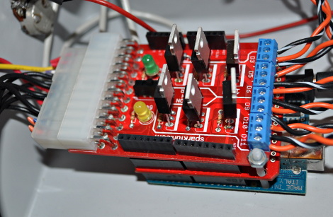
One of the many nice things about the SparkFun Power MosFet shield, is that its very easy to use. Especially when wiring up the hacked computer power supply to it. This particular shield is intended to have 3 of the outputs used with a computer’s 5 volt supply and 3 of the outputs with the 12 volt supply. In my case, I wanted to use all 6 outputs with the 12 volt supply. This is really easy to do. Just cut the ATX connector off of the power supply you are going to use, but leave enough wire on the connector and power supply end to re-wire it up.
Then take the ATX plug and tie the yellow wire that is on pin 10 of the ATX connector to the red wire that is on pin 4 of the ATX connector. then take the yellow wire that is coming out of the Computer power supply (this is the +12 volt wire) and tie it to the two wires I just mentioned.
Here is what is going on. The Sparkfun MosFet shield is set up for half of the board to use 12 volts and the other half to use 5 volts. In my case, I need 12 volts for all six channels of the color organ. So in tying pin 10 to pin 4 together, I am using 12 volts on all six of the Power MosFet shield.
In the diagram below the red wire connects pin 10 to pin 4.
When assembling the shield to the Arduino, put the Sparkfun Spectrum Board on first, then the SparkFun Power MosFet shield on last. Here is a photo of them assembled inside the Color Organ box.
For the outputs of the Power MosFet board, I used ¼ inch phone jacks that you can get at Radio Shack. The main reason for this is that they are readily available and inexpensive.


Thanks!!
Welcome!