Phasing Harness layout for the HDTV antenna
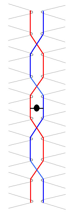 The next thing is to wire up the phasing harness, which connects the HDTV antenna’s driven elements together. The diagram on the left shows how the HDTV antenna’s elements are connected I drew one in blue, and the other one in red for clarity. Also note that where the two cross, they do not touch. If possible keep them separated by 3/4 of an inch.
Also note the black dot in the center of the diagram. This is the feedpoint of the HDTV antenna. The impedance here is 300 ohms. If you are going to feed your HDTV antenna with 75 ohm coax, then you will need to place a CATV transformer, otherwise known as a balun at the feedpoint and then connect your coax to the balun.
I used 14 ga. copper wire for connecting the elements together. The photo below shows how I interlaced the wire through the HDTV antenna elements:
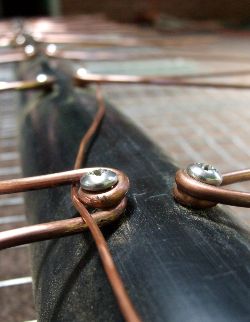
Once all of the elements are connected up, they need to be soldered to the phasing harness. This is important, as my HDTV antenna will be outdoors, and I want the connections to not corrode, which will eventually happen if the joints aren’t soldered together. You will need to use a high wattage soldering gun, as a soldering iron won’t generate enough heat. I used my 140 watt Weller soldering gun. Also don’t worry about the heat melting the PVC pipe. It will soften it up a bit, but if you use a big enough soldering gun that heats up the joint quickly, you will be fine.
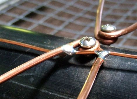
Here is a photo of one of the joints soldered up. As you can see in the photo, a good solder joint should look like this. Smooth and shiny.
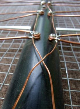
Here is another photo of part of the completed phasing harness. This shows the crossing point. The two wires at this point should not be touching. If possible, try to keep the distance between them 3/4” apart.
Next measure each element from the solder joint (pictured above) to a length of 7 inches and cut it off at this point. After the elements are cut, measure the distance between the tips of the elements. They should all be the same (aprox. 3 inches).
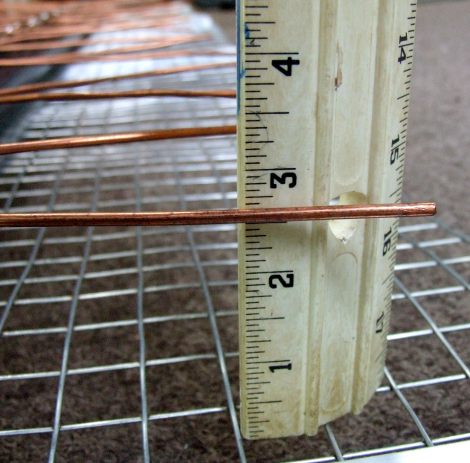
Next you need to measure the distance from the end of each element to the reflector and bend the elements so that they are 2 1/2 inches away from the reflector. Use a pair of vice grips on the screw that hold the element to the PVC pipe while bending the element.
At the center point of the phasing harness, attach a 75 – 300 ohm balun. Make sure it has a weather boot as well since it will be outside.
I am very happy with my HDTV antenna I have built. I also recommend adding a mast mounted preamp. One in particular I like is built by Kitz Technologies. Specifically the KT-200. I am able to consistently pick up TV stations over 70 miles away, and sometimes TV stations over 100 miles away.
This article was originally posted on www.mikestechblog.com Any reproduction on any other site is prohibited and a violation of copyright laws.
I cut cable about two years ago and made an antenna (inside) similar to the one posts using copper wire as clothes hangers attached . on a thin piece of wood . I am able to get 39 channels. It truly worked better than the Purchased antenna.When my grandson saw how well it worked he was amazed and had that can you make me one on his face. Now that I see your model , I’m wondering if I up grade mine with wire and pipe as yours if it may be more effective.
Hello,
The more elements that the antenna has the more gain it will have. Which will allow you a greater range. So if your antenna you built has less elements than mine, then adding elements will increase the gain of the antenna and will increase its range.
Good luck!
— Mike WB8ERJ
How did you mount to your roof
Hello,
I have a 30 foot tower that I mounted it on.
would this work in an attic?
B
Yes, but not as good as if it was outside. This antenna is somewhat tall. Something close to 8 feet.
Good luck!
Where’s the wire going to the TV set?
Ah! Good question! It seems that I didn’t put in the text on page 7. If you look at the diagram showing the layout of the phasing harness, in the center is a black dot. That is where you connect the feed point, which is 300 ohms. Since most people use coax (recommended..) you will need to connect a CATV transformer. Otherwise known as a CATV balun. Then run your Coax down to the TV.
Good catch! I will update page 7 to properly answer your question.
— Mike WB8ERJ
Any chance you could provide a picture of the balun connection? Is a simple 75 to 300 Ohm transformer (like this: https://www.parts-express.com/75-to-300-Ohm-Matching-Transformer-180-010?quantity=1) what you used? Where did you source the animal fencing?
Hello,
Sorry, I don’t have a picture of the balun connection. Yes, the balun is a simple 75 to 300 ohm transformer like the one you link. They can be found pretty much anywhere. Walmart, Home Depot etc.
As far as the fencing, I picked min up at Tractor Supply. Any farm type supply stor will have it.
Does this pick up both VHF and UHF frequencies? What sort of gain do you observe with VHF and with UHF frequencies?
Since the move to HDTV, all TV channels are UHF even though the old VHF channels kept their original channel numbers.
As far as gain observed, I have no way of measuring TV antenna gain. What I can tell you is that my HDTV antenna is on top of a 30 foot tower and I get a clear picture from several stations 70 miles away.
Hope this helps! — Mike
I’m very interested in the antenna since analog tv broadcasts have ended in my country.
But ‘imperial’ sizes are as good as unknown in Europe.
Okay I know 1 inch = 1 thumb and equals 3,54 cm
1 ft = 30,48 cm
more difficult is the thickness of the copper wire, so what is ‘ga’ ?
The balun or transformer seems difficult to find here, how does it look like ?
Who helps ?
Hello, thanks for reading my blog.
First of all, 1 inch = 2.54 cm instead of 3.54 cm like you mentioned. My guess is its just a mis-typing, but I wanted to be clear.
You make a good point about Imperial sizes, especially about wire size. Below I have listed the wire diameters in mm for you.
6ga wire = 4.11 mm
14ga wire = 1.63 mm
These wire sizes aren’t critical. The main reason for using the 4.11 mm wire for the elements is so it can withstand high winds without bending.
As far as the balun, here is an amazon link with a photo and a description – the balun needs to be UHF frequency range.
https://www.amazon.com/Philmore-Outdoor-Antenna-Matching-Transformer/dp/B01B1VSCK6
Hope this helps! Good luck!
— Mike WB8ERJ
This design seems directional. I live in the middle of towers that are about the same distance apart. Linn Creek, MO 65052. Is there something you can recommend that is multi directional or can I put the same design on the backside of the reflectors?
Thanks for your time Stephen Houska.
Hello, yes, this is very directional. In order to pick up stations from different directions you will need an antenna rotor to rotate in the direction of the station you want to receive.
I wonder if galv. fencing could be rolled into a cylinder and used for antenna elements?
I kind of doubt it.
Can you connect multiple antennas to each other to compensate for having to aim in different directions?
Hello, I suppose you could. I’m not sure how well it would work out though. Honestly a better solution is to use an antenna rotator.
Hi,
I am thinking of doing this for a attic location. I would like to use 1/2″ square hardware cloth for my reflector. Would I still need the 2-1/2″ spacing to the elements or would this change for the 1/2″ square holes?
Yes you would still need the 2 1/2 inch spacing to the elements.The hardware cloth would probably be a better reflector than what I used. I decided against hardware cloth because my HDTV antenna is outside and subject to high winds.
Can explain you the the science on how the values were derived for the following items :
* the length of each element (V) for the unbent length? [ you used 18″ folded into V shaped with ~8.9″ for each “wing” ]
* the distance of the wing tips? [ no values stated ]
* the size of the holes in the reflector (mesh/screen)? [ you used 1″ holes ]
* the distance between the left (>) and right (<) elements (V)? [ you used 3/4" ]
* the distance between the each pair of left/right elements ? [ you used 7" ]
Honestly, no science behind it. These are based on commercial antennas that I have looked at.
Since it works for them I figured it would work for me. And it works quite well.
Thanks for reading my blog.
— Mike WB8ERJ
Great article:I already constructed it.
Thanks!