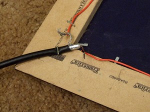
If its not feasible to put this FM antenna in the attic, an alternative would be to take the loop of wire and attach it to the back side of a picture frame.Just make sure the frame is a non-metal one.
This is What i did with the picture below:

Even though the picture isn’t square, your indoor FM antenna will still work fine. Just so long as your total wire length is 120 inches.
So all you have to do in this case, is take the picture off the wall and staple the loop to the back of the picture as shown in the photo below:

I just used my staple gun with ½ inch staples. I started with the coax, and then worked my way around the picture frame. There still the issue of being able to see the coax. In order to help hide it, I suggest painting the coax the same color as the wall.
As far as directivity of this indoor FM antenna, its greatest sensitivity is perpendicular to the plane of the loop.
This article was originally posted on www.mikestechblog.com Any reproduction on any other site is prohibited and a violation of copyright laws
so curious….. i love this idea of a fulll wave antenna, going to make one with a total wire length of 131.5 inches because all i want is classical/jazz folk public radio and college stations between 89 and 91 MHz. Your calculation appears to be based on mid-FM 97.5 MHz. Please correct me if I am wrong to make it 131 inches. My curiosity is why the feedline is 75 ohm coax and not 300 ohm twin lead?? what makes this 75 ohms??
Hello, you obviously used the formula for calculating the length of a full wave loop. Well done! With receiving antennas the length / resonant frequency of an antenna is not as critical as for a transmitting antenna. You are correct, in the my suggested lengths are for the middle of the FM band. However it still covers the entire FM band quite satisfactorily.
Making the loop the length you suggest will work just fine but making the loop the length I made mine also works fine around 90 mHz, which like you, I was also interested in receiving a station at 90.7 mHz. Either length will work just fine.
Concernig the use of 300 ohm twinlead, the impedance for a full wave loop is 100 ohms so 75 ohm coax is a closer match. You could probably use 300 ohm twinlead and it would still work just fine. Most stereo’s have a way to accept either 300 ohm twinlead or 75 ohm coax. If your stereo only accepts 300 ohm twinlead, then get a 75 ohm to 300 ohm adapter.
Hope this helps – good luck!
— Mike WB8ERJ
FINALLY got to try this… used PVC because I had it.. significant improvement over folded dipole but not yet perfect…. better enough to try several tuners I have… Also considering trying a circle (hula hoop maybe??) and if the circle works as well as the square, I’ll try thin copper tubing from a plumbing supply house, (maybe like for kerosene delivery – rather thin copper) or possibly something like 12 guage electrical wire so that I can put this outside (a shame my 2 meter antenna is on an aluminum mast. Will continue to have fun tinkering, thanks for the nudge in the right direction. A couple questions: Is there a thickness of conductor not to be exceeded? Might a tuning capacitor help?? Thanks again!!!! 73 Peter
Good to know it works better than a folded dipole. As far as trying different shapes, from what I have read concerning full wave loop antennas, for maximum gain the shape with the largest area inside the loop is the way to go. So the question is what contains the largest area inside the loop, the circle or the square. My guess is that there will be a slight improvement, but how much would be a good experiment. If you try this, please let me know in the comments.
As far as conductor thickness there is no limit. If you can afford it, large diameter copper pipe would work just as well.
I don’t think a tuning capacitor would help since the antenna is already pretty much matched to the coax. A full wave loop has an impedance of around 100 ohms, which for receiving is close enough to 75 ohm coax to work just fine.
Good luck and have fun!
— Mike WB8ERJ
Update… I got 50 feet of #8 solid copper for something like 25 bucks… the diamond configuration performs audibly better than the #20 (or maybe it was 21) gauge wire. soldering to it was the biggest problem – it demonstrated copper’s great heat conductivity! it is almost good enough to just sit in the window and not have to rotate except for those darned metal miniblinds! So now I am just going to HAVE to try the circle with the better conductor
Kudos! Works like a charm. Improved my reception 100%. FM preference was 88.7 to 90.5 so far so good.
Awesome! Glad it worked for you. Lots of people have built this antenna and have had similar results.
Happy listening!
— Mike
2 questions: Can stranded copper speaker cable work for the wire, probably 2 runs of 16 gauge in the speaker cable? Can this be done without soldering? That is the only thing I would have to buy, I thought wire nuts might work but the shield to stranded wire connection would be the tricky one. Or maybe just a good excuse to get a soldering iron again, I did have one somewhere….
Hello, yes speaker wire is just fine. Actually any wire is fine.
Concerning your second question, soldering isn’t necessary. Just twisting them together with your fingers will work. The down side is that it isn’t as mechanically strong as soldering so after a period of time it might come apart.
Good luck!
— Mike WB8ERJ
Yikes! The only thing I had to buy was a 300 to 75 ohm transformer for my 55 year old, 11 tube Dynaco PA 3 tuner that had been sitting at friend’s house out of town for the last 45 years unused. I’m in a basement apt in a house with a 450 sq. ft. covered area outside my door. I put the antenna outside in the covered space pointed at GA Tech University and now I can get WREK and WRFG (Radio Free Georgia) and even WCLK Clark Atlanta University with a great signal! Many thanks, and easy to go without solder, used a wire nut for the middle conductor to the stranded speaker wire and some electrical tape for the shield which bundled nicely. I built in strain relief so no chance for it to come apart. Thanks at least a million! When I built a house I installed an antenna 40 ft up on the roof and bought a Radio Shack rotor and this is nearly as good!
Hey thanks for checking back with your excellent report! Glad it worked so well for you – Happy listening!
— Mike WB8ERJ
Any suggestions on how to improve the FM singinal on the Single Wire FM Antenna, that comes standard on most stereos.
Hello, sorry but no. Those antennas are the worst possible antenna for receiving an FM signal.
I have a Tecsun PL-880 equipped with a telescoping whip antenna for FM. The radio only has an antenna input for a SW antenna (3.5mm mini plug), and uses a ferrite bar for MW. The manual suggests simply using an alligator clip to connect an external FM antenna, which I assume would be the center conductor, which leaves me to wonder where best to connect the other lead from the coax braid. One article I came across suggested attaching to the radio chassis, which of course would require dismantling the radio. And once in there, I’d probably find that the radio uses a PCB rather than a chassis. As a work-around, the article suggested connecting to the outer ring of any available plug receptacle, which in the case of the PL-880, would be the SW antenna input. Sound like the best option to you? Making a connection by that method will require some sort of conically shaped plug, that connects to the outer ring, but not the center conductor.
Hello,
What you are suggesting sounds reasonable however I am not familiar with the Tecsun radio you mention. So honestly I can’t really say.
Good luck!
Would 22 AWG work fine, or is a greater conductor thickness important? Also does the cable on the antenna need to be taut, and is it important to run the coax down the middle or is it just for aesthetic purposes? Thanks for the guide
Yes, really any wire will work just fine.
What is the gain of this antenna?
I don’t know. but I am getting a good signal from stations 70 miles away.